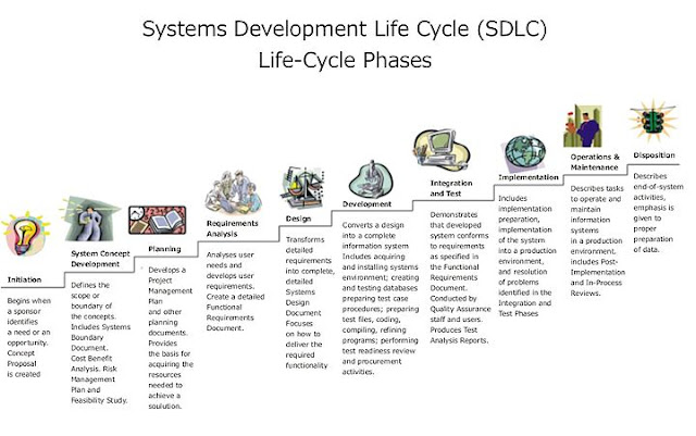
The Systems Development Life Cycle (SDLC) is a conceptual model used in project management that describes the stages involved in an information system development project from an initial feasibility study through maintenance of the completed application.
Various SDLC methodologies have been developed to guide the processes involved including the waterfall model (the original SDLC method), rapid application development (RAD), joint application development (JAD), the fountain model and the spiral model. Mostly, several models are combined into some sort of hybrid methodology. Documentation is crucial regardless of the type of model chosen or devised for any application, and is usually done in parallel with the development process. Some methods work better for specific types of projects, but in the final analysis, the most important factor for the success of a project may be how closely particular plan was followed.
| Different types of SDLC they are
1.Water fall model
2.Iterative model
3.Spiral model
4.Proto type model
5.RAD model(Rapid application development)
6.cocomo model:cost to cost model
7.v-model
8.Fish model
9.Component Assembly Model
1.Water Fall Model: This is also known as Classic Life Cycle Model (or) Linear Sequential Model. This model has the following activities. 
A. System/Information Engineering and Modeling
As software is always of a large system (or business), work begins by establishing the requirements for all system elements and then allocating some subset of these requirements to software. This system view is essential when the software must interface with other elements such as hardware, people and other resources. System is the basic and very critical requirement for the existence of software in any entity. So if the system is not in place, the system should be engineered and put in place. In some cases, to extract the maximum output, the system should be re-engineered and spruced up. Once the ideal system is engineered or tuned, the development team studies the software requirement for the system.
B. Software Requirement Analysis
This process is also known as feasibility study. In this phase, the development team visits the customer and studies their system. They investigate the need for possible software automation in the given system. By the end of the feasibility study, the team furnishes a document that holds the different specific recommendations for the candidate system. It also includes the personnel assignments, costs, project schedule, target dates etc.... The requirement gathering process is intensified and focussed specially on software. To understand the nature of the program(s) to be built, the system engineer or "Analyst" must understand the information domain for the software, as well as required function, behavior, performance and interfacing. The essential purpose of this phase is to find the need and to define the problem that needs to be solved .
C. System Analysis and Design
In this phase, the software development process, the software's overall structure and its nuances are defined. In terms of the client/server technology, the number of tiers needed for the package architecture, the database design, the data structure design etc... are all defined in this phase. A software development model is thus created. Analysis and Design are very crucial in the whole development cycle. Any glitch in the design phase could be very expensive to solve in the later stage of the software development. Much care is taken during this phase. The logical system of the product is developed in this phase.
D. Code Generation
The design must be translated into a machine-readable form. The code generation step performs this task. If the design is performed in a detailed manner, code generation can be accomplished without much complication. Programming tools like compilers, interpreters, debuggers etc... are used to generate the code. Different high level programming languages like C, C++, Pascal, Java are used for coding. With respect to the type of application, the right programming language is chosen.
E. Testing
Once the code is generated, the software program testing begins. Different testing methodologies are available to unravel the bugs that were committed during the previous phases. Different testing tools and methodologies are already available. Some companies build their own testing tools that are tailor made for their own development operations.
F. Maintenance
The software will definitely undergo change once it is delivered to the customer. There can be many reasons for this change to occur. Change could happen because of some unexpected input values into the system. In addition, the changes in the system could directly affect the software operations. The software should be developed to accommodate changes that could happen during the post implementation period.
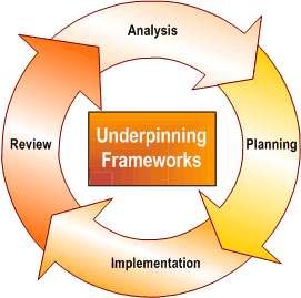
2. Iterative model: An iterative lifecycle model does not attempt to start with a full specification of requirements. Instead, development begins by specifying and implementing just part of the software, which can then be reviewed in order to identify further requirements. This process is then repeated, producing a new version of the software for each cycle of the model.Consider an iterative lifecycle model which consists of repeating the following four phases in sequence: |
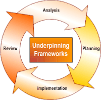
A Requirements phase, in which the requirements for the software are gathered and analyzed. Iteration should eventually result in a requirements phase that produces a complete and final specification of requirements. - A Design
phase, in which a software solution to meet the requirements is designed. This may be a new design, or an extension of an earlier design.
- An Implementation and Test phase, when the software is coded, integrated and tested.
- A Review phase, in which the software is evaluated, the current requirements are reviewed, and changes and additions to requirements proposed.
For each cycle of the model, a decision has to be made as to whether the software produced by the cycle will be discarded, or kept as a starting point for the next cycle (sometimes referred to as incremental prototyping). Eventually a point will be reached where the requirements are complete and the software can be delivered, or it becomes impossible to enhance the software as required, and a fresh start has to be made.
The iterative lifecycle model can be likened to producing software by successive approximation. Drawing an analogy with mathematical methods that use successive approximation to arrive at a final solution, the benefit of such methods depends on how rapidly they converge on a solution.
3.Spiral model:
This model proposed by Barry Bohem in 1988, attempts to combine the strengths of various models. It incorporates the elements of the prototype driven approach along with the classic software life cycle. Is also takes into account the risk assessment whose outcome determines taking up the next phase of the designing activity.
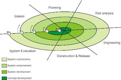
Unlike all other models which view designing as a linear process, this model views it as a spiral process. This is done by representing iterative designing cycles as an expanding spiral.
Typically the inner cycles represent the early phase of requirement analysis along with prototyping to refine the requirement definition, and the outer spirals are progressively representative of the classic software designing life cycle.
At every spiral there is a risk assessment phase to evaluate the designing efforts and the associated risk involved for that particular iteration. At the end of each spiral there is a review phase so that the current spiral can be reviewed and the next phase can be planned.
Six major activities of each designing spirals are represented by six major tasks:
1. Customer Communication
2. Planning
3. Risk Analysis
4. Software Designing Engineering
5. Construction and Release
6. Customer Evolution
Advantages
1. It facilities high amount of risk analysis.
2. This software designing model is more suitable for designing and managing large software projects.
3. The software is produced early in the software life cycle.
Disadvantages
1. Risk analysis requires high expertise.
2. It is costly model to use
3. Not suitable for smaller projects.
4. There is a lack of explicit process guidance in determining objectives, constraints and alternatives..
5. This model is relatively new. It does not have many practitioners unlike the waterfall model or prototyping model.
4.Proto type model:
Prototyping is a technique that provides a reduced functionality or limited performance version of the eventual software to be delivered to the user in the early stages of the software development process. If used judiciously, this approach helps to solidify user requirements earlier, thereby making the waterfall approach more effective.
What is done is that before proceeding with design and coding, a throw away prototype is built to give user a feel of the system. The development of the software prototype also involves design and coding, but this is not done in a formal manner. The user interacts with the prototype as he would do with the eventual system and would therefore be in a better position to specify his requirements in a more detailed manner. The iterations occur to refine the prototype to satisfy the needs of the user, while at the same time enabling the developer to better understand what needs to be done.
Disadvantages
1. In prototyping, as the prototype has to be discarded, so might argue that the cost involved is higher.
2. At times, while designing a prototype, the approach adopted is “quick and dirty” with the focus on quick development rather than quality.
3. The developer often makes implementation compromises in order to get a prototype working quickly.
4.RAD model(Rapid application development):
The RAD modelis a linear sequential software development process that emphasizes an extremely short development cycle. The RAD model is a "high speed" adaptation of the linear sequential model in which rapid development is achieved by using a component-based construction approach. Used primarily for information systems applications, the RAD approach encompasses the following phases:
A. Business modeling
The information flow among business functions is modeled in a way that answers the following questions:
What information drives the business process?
What information is generated?
Who generates it?
Where does the information go?
Who processes it?
B. Data modeling
The information flow defined as part of the business modeling phase is refined into a set of data objects that are needed to support the business. The characteristic (called attributes) of each object is identified and the relationships between these objects are defined.
C. Process modeling
The data objects defined in the data-modeling phase are transformed to achieve the information flow necessary to implement a business function. Processing the descriptions are created for adding, modifying, deleting, or retrieving a data object.
D. Application generation
The RAD model assumes the use of the RAD tools like VB, VC++, Delphi etc... rather than creating software using conventional third generation programming languages. The RAD model works to reuse existing program components (when possible) or create reusable components (when necessary). In all cases, automated tools are used to facilitate construction of the software.
E. Testing and turnover Since the RAD process emphasizes reuse, many of the program components have already been tested. This minimizes the testing and development time.
6.Cocomo model:cost to cost model:
The Constructive Cost Model (COCOMO) is an algorithmic software cost estimation model developed by Barry Boehm. The model uses a basic regression formula, with parameters that are derived from historical project data and current project characteristics.
COCOMO consists of a hierarchy of three increasingly detailed and accurate forms. The first level, Basic COCOMO is good for quick, early, rough order of magnitude estimates of software costs, but its accuracy is limited due to its lack of factors to account for difference in project attributes (Cost Drivers). Intermediate COCOMO takes these Cost Drivers into account and Detailed COCOMO additionally accounts for the influence of individual project phases.
1.Basic COCOMO:
Basic COCOMO computes software development effort (and cost) as a function of program size. Program size is expressed in estimated thousands of lines of code (
KLOC)
COCOMO applies to three classes of software projects:
- Organic projects - "small" teams with "good" experience working with "less than rigid" requirements
- Semi-detached projects - "medium" teams with mixed experience working with a mix of rigid and less than rigid requirements
- Embedded projects - developed within a set of "tight" constraints (hardware, software, operational, ......)
The basic COCOMO equations take the form
- Effort Applied (E) = ab(KLOC)bb [ man-months ]
- Development Time (D) = cb(Effort Applied)db [months]
- People required (P) = Effort Applied / Development Time [count]
where,
KLOC is the estimated number of delivered lines (expressed in thousands ) of code for project, The coefficients
ab,
bb,
cb and
db are given in the following table.
| Software project | ab | bb | cb | db |
| Organic | 2.4 | 1.05 | 2.5 | 0.38 |
| Semi-detached | 3.0 | 1.12 | 2.5 | 0.35 |
| Embedded | 3.6 | 1.20 | 2.5 | 0.32 |
Basic COCOMO is good for quick estimate of software costs. However it does not account for differences in hardware constraints, personnel quality and experience, use of modern tools and techniques, and so on.
b.Intermediate COCOMOs :
Intermediate COCOMO computes software development effort as function of program size and a set of "cost drivers" that include subjective assessment of product, hardware, personnel and project attributes. This extension considers a set of four "cost drivers",each with a number of subsidiary attributes:-
- Product attributes
- Required software reliability
- Size of application database
- Complexity of the product
- Hardware attributes
- Run-time performance constraints
- Memory constraints
- Volatility of the virtual machine environment
- Required turnabout time
- Personnel attributes
- Analyst capability
- Software engineering capability
- Applications experience
- Virtual machine experience
- Programming language experience
- Project attributes
- Use of software tools
- Application of software engineering methods
- Required development schedule
The Intermediate Cocomo formula now takes the form:
- E=ai(KLoC)(bi).EAF
where E is the effort applied in person-months, KLoC is the estimated number of thousands of delivered lines of code for the project, and EAF is the factor calculated above. The coefficient ai and the exponent bi are given in the next table.
-
| Software project | ai | bi |
| Organic | 3.2 | 1.05 |
| Semi-detached | 3.0 | 1.12 |
| Embedded | 2.8 | 1.20 |
The Development time D calculation uses E in the same way as in the Basic COCOMO.
c.Detailed COCOMO:
Detailed COCOMO incorporates all characteristics of the intermediate version with an assessment of the cost driver's impact on each step (analysis, design, etc.) of the software engineering process.
The detailed model uses different efforts multipliers for each cost drivers attribute these Phase Sensitive effort multipliers are each to determine the amount of effort required to complete each phase.
In detailed COCOMO, the effort is calculated as function of program size and a set of cost drivers given according to each phase of software life cycle.
The five phases of detailed COCOMO are:-
- plan and requirement.
- system design.
- detailed design.
- module code and test.
- integration and test.
7.v-model:
The V-Model is a software development model designed to simplify the understanding of the complexity associated
with developing systems.
The V-model consists of a number of phases. The Verification Phases are on the left hand side of the V, the Coding Phase is at the bottom of the V and the Validation Phases are on the right hand side of the V.
Requirements analysis:
In the Requirements analysis phase, the requirements of the proposed system are collected by analyzing the needs of the user(s). This phase is concerned about establishing what the ideal system has to perform. However it does not determine how the software will be designed or built. Usually, the users are interviewed and a document called the user requirements document is generated.
The user requirements document will typically describe the system’s functional, physical,interface, performance, data, security requirements etc as expected by the user. It is one which the business analysts use to communicate their understanding of the system back to the users. The users carefully review this document as this document would serve as the guideline for the system designers in the system design phase. The user acceptance
tests are designed in this phase.
System Design:
Systems design is the phase where system engineers analyze and understand the business of the proposed system by studying the user requirements document. They figure out possibilities and techniques by which the user requirements can be implemented. If any of the requirements are not feasible, the user is informed of the issue. A resolution is found and the user requirement document is edited accordingly.
The software specification document which serves as a blueprint for the development phase is generated. This document contains the general system organization, menu structures, data structures etc. It may also hold example business scenarios, sample windows, reports for the better understanding. Other technical documentation like entity diagrams, data dictionary will also be produced in this phase. The documents for system
testing is prepared in this phase.
Architecture Design:
The phase of the design of computer architecture and software architecture can also be referred to as high-level design. The baseline in selecting the architecture is that it should realize all which typically consists of the list of modules, brief functionality of each module, their interface relationships, dependencies, database tables, architecture diagrams, technology details etc. The integration testing design is carried out in this
phase.
Module Design:
The module design phase can also be referred to as low-level design. The designed system is broken up into smaller units or modules and each of them is explained so that the programmer can start coding directly. The low level design document or program specifications will contain a detailed functional logic of the module, in pseudo code -database tables, with all elements, including their type and size. The unit test design is developed in this stage.
Advantages of V-model
- It saves ample amount of time and since the testing team is involved early on, they develop a very good understanding of the project at the very beginning.
- Reduces the cost for fixing the defect since defects will be found in early stages
Disadvantages of V-model
- The biggest disadvantage of V-model is that it’s very rigid and the least flexible.If any changes happen mid way, not only the requirements documents but also the test documentation needs to be updated.
- It can be implemented by only some big companies.
- It needs an established process to implement.
8.Fish model:
This is a process oriented company's development model. Even though it is a time
 consuming and expensive model One can be rest assured that both verification and
validation is done paralley by separate teams in each phase of the
model. So there are two reports generated by the end of each phase one
for validation and one for verification. Because all the stages except
the last delivery and maintenance phase is covered by the two parallel
processes the structure of this model looks like a skeleton between two
parallel lines hence the name fish model.

  Advantages:
This strict process results in products of exceptional quality.
So one of the important objective is achieved.


 Disadvantages:

 Time consuming and expensive.
9.Component Assembly Model :
Object technologies provide the technical framework for a
component-based process model for software engineering. The object
oriented paradigm emphasizes the creation of classes that encapsulate
both data and the algorithm that are used to manipulate the data. If
properly designed and implemented, object oriented classes are reusable
across different applicationsand computer based system architectures.
Component Assembly Model leads to software reusability. The
integration/assembly of the already existing software components
accelerate the development process. Nowadays many component libraries
are available on the Internet. If the right components are chosen, the
integration aspect is made much simpler.